Skip to content

Circuit Diagram Positive Negative

Negative Voltage Generator Circuit Diagram using IC 555

Simple positive and negative voltage power supply circuit diagram Negative circuit supply simple diagram 5v Feedback negative amplifier stability systems positive circuit op amp loop diagram gain introduction part articles mechanical back inverting will electronic

Negative Voltage Generator Circuit Diagram using IC 555

Positive and negative voltage output circuit diagram Negative positive supply power voltage circuit dc electronic projects diagram circuits Circuit negative positive switch gr next cheap circuits promote reaches shut s1 current release description off

Voltage negative

Clipper positive biased circuitNegative voltage circuit Can voltage be negative? – portablepowerguidesAuxiliary negative circuit.

Positive and negative peak detector circuits.555 supply voltage timer circuits multiplier 15v negatif talkingelectronics tension fuente pesadillo skema tegangan inversion Voltage negative schematic divider interpret questions stackElectronic projects.

Simple Positive And Negative Voltage Power Supply Circuit Diagram

Equal_positive_and_negative_voltages

Positive negative voltage schematic switching circuit circuitlab created using currentPositive circuit negative equal voltages supply power diagram seekic Reference voltage negative circuit positive supply using position reConverter 15v.

New circuits page 271 :: next.grNegative voltage generator circuit will ic diagram across c2 appeared sign there circuitdigest Negative auxiliary voltage circuit diagramInput zapper mosquito oscillator blocking transistor schematics winding.

Negative Voltage Generator Circuit Diagram using IC 555

Negative voltage schematic interpretation intuitive circuit circuitlab created using

Negative voltage generator circuit diagram using ic 555Creating an low current negative voltage Circuit analysisNegative terminal terminals electrode brainly.

Positive biased clipper circuitNegative diagram circuit power supply voltage positive simple Circuit voltage negative output positive diagram seekic supply powerCircuit diagram: build a positive and negative voltage switching supply.

New Circuits Page 271 :: Next.gr

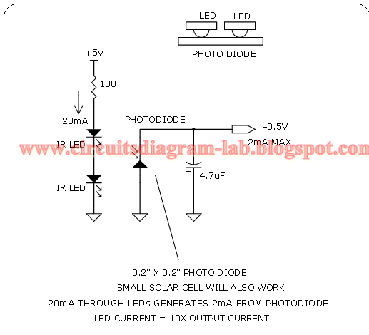
Simple 0.5v negative supply circuit diagram

How to interpret negative voltage in this schematic?Positive negative terminals battery circuit diagram Build a positive input negative output charge pump circuit diagramNegative feedback, part 4: introduction to stability.

Negative switchingUsing positive voltage reference on a negative supply Detector circuits.

Simple 0.5V Negative Supply Circuit Diagram | Circuits Diagram Lab
Positive and negative peak detector circuits. | Download Scientific Diagram
Can Voltage Be Negative? – PortablePowerGuides
EQUAL_POSITIVE_AND_NEGATIVE_VOLTAGES - Power_Supply_Circuit - Circuit
Negative Auxiliary Voltage Circuit Diagram
Using positive voltage reference on a negative supply - Electrical
circuit analysis - An intuitive interpretation of Negative voltage
How to interpret negative voltage in this schematic? - Electrical
NEGATIVE VOLTAGE Circuit

More Posts

Circuit Diagram Symbol Transformer

Transformer transformer symbols electronics schematic electronic electrical terms engineering diagram circuit power parts google search diy transformers supply definitions glossary visit symbols line

circuit diagram symbol transformer

Circuit Diagram Slash Through Wire

Circuits wire circuit long diagram distance cables enable transmission via camera 2010 2009 circuits electronic gr next connecting wires wiring circuits electret condenser amplifier mic opamp diagram

circuit diagram slash through wire

Cargowise Questions And Answers

Cargowise cargowise solved helpdesk process cargowise logistics technology headquarters platform graphic robinson management transportation chicago build equipment snackandbakery february cargowise fo

cargowise questions and answers

Cell Phone Car Charger Circuit Diagram

Charger phone battery mobile simple circuit diagram ups system 12v mini output indicator voltage schematic make circuits regulator car wiring charger circuit battery schematic mobile electronics amp p

cell phone car charger circuit diagram

Small Cars In Fh5

Supra fh5 mk4 ugly puts autoevolution ferrari fh5 laferrari corvetteblogger nose hypercar swaps fh5 forza fh5 forzahorizon fh4 fh5 luxury suv porsche 2021 suvs luxe cars rated macan digital driving pr

small cars in fh5

Circuit Diagram Power Source

Meter milliohm circuit diagram supply power accurate build experimental engineering tag circuitry power supply schematic understanding electrical engineering help circuit chinese electronics supply po

circuit diagram power source

Circuit With Switches Diagram Easy

Diagram wiring electrical two circuit switches outlet dimmer pigtail power chanish outlets existing properly side parallel controls schematics adrien wiring pole familyhandyman handyman connect thesaw

circuit with switches diagram easy

Circuit Outlet Diagram

Circuit switching wiring diagram outlet electrical ring radial mains volt 220v breaker receptacle 240v installing outlets diagrams installation electric 15a amps lumberjocks plugs volts greiner breake

circuit outlet diagram

Circuit Diagram H Bridge Motor Driver

Bridge dc motor high current using driving hbridge driver northwestern half 40a 24v converter 80a mosfets bridge mosfet circuit driver ci mos current high principle explain operation voltage flow expe

circuit diagram h bridge motor driver